Volkswagen Tiguan Service and Repair Manual: Rearview Camera System
General Information
Note
- Familiarity with the function and operation of the rearview camera system is needed if there are customer concerns.
- Refer to Owner's Manual.
- Use the Vehicle Diagnostic Tester in "Guided Fault Finding" when servicing or performing Fault Finding.
- When the battery is connected, check the all the vehicle accessories (radio, clock, electronic conveniences, etc.) according to the repair manual and/or the Owner's Manual.
The rear system assists the driver during back-up driving by providing the driver with an image of the traffic situation behind the vehicle via the monitor of the radio or radio navigation system.
The system switches itself on when the reverse gear is selected, even when the radio or radio/navigation system is switched off.
The rear view camera system consists of the following components:
- The Rearview Camera -R189-,
- The Rearview Camera System Control Module -J772-
- the Radio/Navigation Display Unit Control Module -J503-,
- and steering wheel with Steering Angle Sensor -G85-.
Note
It is not permitted to install an auxiliary license plate holder for vehicles with rear view camera system because it would impair the function of the rear view camera system. License plate lights may also be impaired.
Malfunction Recognition and Malfunction Indicator:
The rearview camera system is equipped with on board diagnostic.
Use the Vehicle Diagnostic Tester in "Guided Fault Finding".
Overview - Rearview Camera System
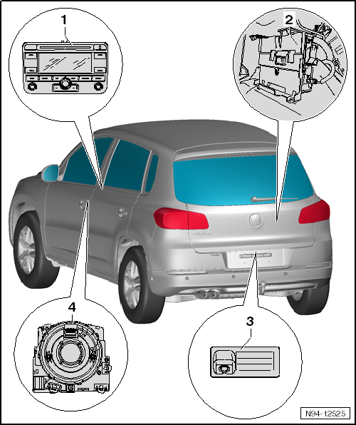
- Radio/Navigation Display Unit Control Module -J503-
- Component location: in the front center console
- Removing and installing.
- Rearview Camera System Control Module -J772-
- Component location: in the luggage compartment behind the right side trim panel
- Removing and installing.
- Rearview Camera -R189-
- Component location: in the rear lid handle button
- Removing and installing.
- Nut tightening specification: 6 Nm
- Rearview Camera System, Calibrating.
- Steering Angle Sensor -G85-
- Component location: in the steering column electronics control module behind the steering column switch trim panel on the steering wheel
- Steering Column Electronics Control Module, Removing and Installing.
Rearview Camera, Removing and Installing
Handle Button with Rearview Camera, Removing from Rear Lid
The rearview camera is installed inside the rear lid handle button. Do not disassemble the handle button. The entire handle button must be replaced.
Rearview Camera System Control Module -J772-
Rearview Camera System Control Module -J772-, Removing and Installing
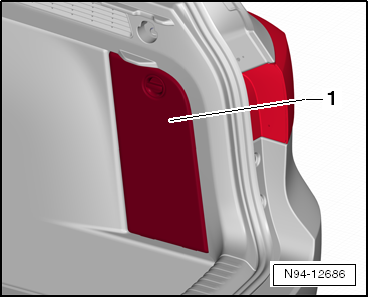
Control module is installed in luggage compartment behind right side wall trim inside the luggage compartment.
Removing
- Switch off the ignition and all electrical consumers and remove the ignition key.
- Open the door -1-.
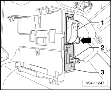
- Unlock and disconnect the connectors -1- and -2-.
- Press the button -arrow- and remove the Rearview Camera System Control Module -J772--3- out of the mount.
Installing
Install in reverse order of removal.
Only if the control module was replaced:
- Calibrate the system again.
Rearview Camera System Control Module -J772-, Coding
- Code the Rearview Camera System Control Module -J772- using the Vehicle Diagnostic Tester.
Rearview Camera System, Calibrating
Preliminary Work for Calibration
Special tools and workshop equipment required
- Calibration Unit -VAS6350A-
After performing service work on the vehicle, it may be necessary to calibrate the rear view camera system anew. In detail, this is the case after:
- Removing and installing rear view camera
- Replacing the rearview camera system control module
- After repair work performed on rear lid following an accident
- After the standing height of one axle changes by more than 5 mm
- After the standing height of the entire vehicle changes by more than 10 mm
There is much preparation work that must be performed before calibrating using the Vehicle Diagnostic Tester. This is described in the following.
Vehicle must stand on a firm and level surface to perform the calibration. No persons may be in the vehicle interior during the measurement. Vehicle must not be moved during the measurement, opening and closing of vehicle doors is to be avoided.
Connect the Vehicle Diagnostic Tester.
- Move the Steering Angle Sensor -G85- into the 0 position (wheels straight ahead).
Overview of the assembled measuring device:
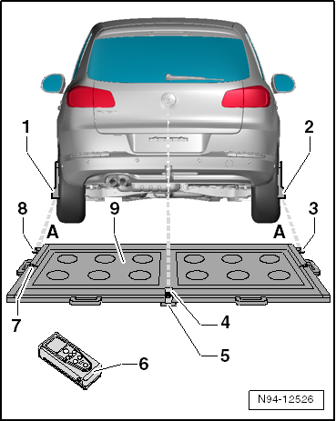
- Calibration Tool - Wheel Center Mountings -VAS6350/1-
- Calibration Tool - Wheel Center Mountings -VAS6350/1-
- Right Angle Bracket for Mounting Measuring Unit for Distance Measurement
- Calibration Tool - Linear Laser -VAS6350/3-
- Switching on and off. Refer to operating instructions.
- Plastic Foot
- Total of three on the bottom side of measuring device
- Adjustable, for aligning horizontal position of measuring device
- Calibration Tool - Spacing Laser -VAS6350/2-
- Notes on operation. Refer to the operating instructions.
- Level on Measuring Device
- For checking horizontal position of measuring device
- Left Angle Bracket for Mounting Measuring Unit for Distance Measurement
- Calibration Unit -VAS6350A-
- Distance between the angled brackets on the calibration device (-item 3- or -item 8-) and the paddles on the rear wheel center mountings: 1.2 m - 1.7 m -dimension A-
- Secure the holed circle "112" on the wheel center sensor with the 3 wheel bolt adapter (17 mm).
- Place the paddles on both wheel center sensors and secure them with locking nuts.
- Place the wheel center sensor on the wheel bolts on the rear wheels. The wheel center mountings are positioned by the "O-rings" in the adapters and held in place.
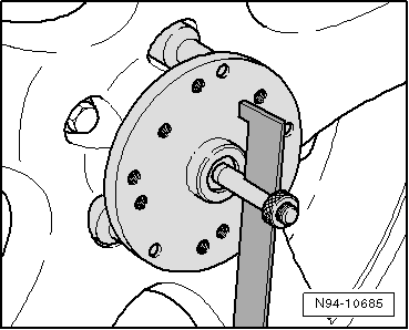
Note
Attach the wheel pick-ups onto wheels so that any installed "anti-theft wheel mounting bolts" are not connected to the wheel bolt adapters.
- Adjust the paddle with aid of lock nuts so that they move freely just above the floor.
Note
- Make sure the paddle moves easily.
- The paddles must return to a vertical position by themselves.
- Position the Calibration Tool -VAS6350- behind the vehicle as illustrated in the overview illustration -dimension A-, -item 9- 1.20 m - 1.70 m between the brackets on the calibration tools and the paddles on the wheel center sensor on the rear wheels.
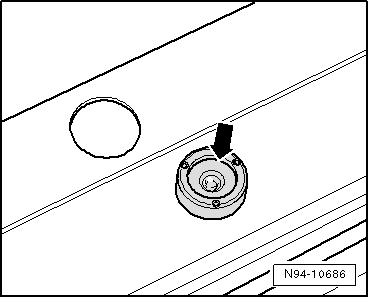
- Bring the Calibration Tool -VAS6350- into a horizontal position. Twist plastic feet under calibration platform so that air bubble in the level is located exactly in the center of the indicator -arrow-.
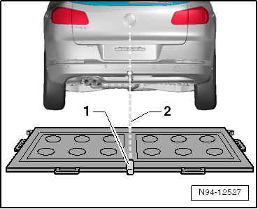
- Turn on the laser on the calibration tool -1- and align the entire calibration tool so that the laser beam -2- is pointed on the center of the rear lid above the VW logo.
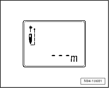
- Turn the Calibration Tool - Spacing Laser -VAS6350/2- for the distance measurement on with the ON button. The following display appears and laser switches itself on:
- Hold distance laser for distance measurement -2- flush into angle bracket on one side of calibration device as shown in the illustration, distance laser must make contact firmly on angle bracket when doing this.
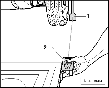
- Make sure that the laser beam from the distance laser for distance measurement contacts the paddle -1- at the lower, enlarged part.
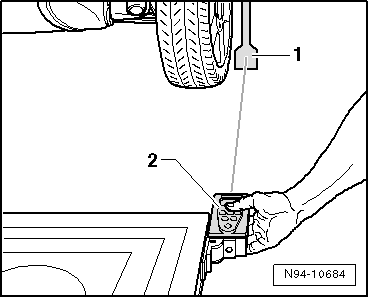
If this is not the case, paddles must be corrected accordingly via clamping screws on the wheel pick-ups.
- Hold the distance laser for distance measurement firmly by the hand in the angle bracket on the measuring device while the laser beam can be seen on the paddle. Briefly press ON button for distance measurement. When doing this, the following display appears on screen:
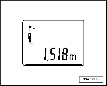
The distance measurement is specified on the display in "meters".
- Note down the distance measured.
- Repeat this measurement on the other side of the calibration tool in the same way for the other rear wheel.
The distance value must be the same on both sides. If the value is not identical, align the calibration device only as long until the values on both sides are identical.
When aligning the calibration device, make sure the line laser beam still strikes the center above the VW emblem and the indicator on the level is still centered. Adjust if necessary.
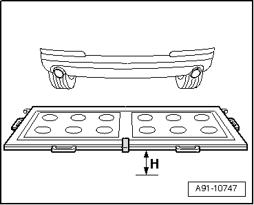
- Measure the height of the calibration device, dimension -H- (top edge platform - floor).
The distance dimension A that was measured, the height of the calibration device -H- and the height of the center of the rearview camera lens to the floor dimension -B- must be entered in the Vehicle Diagnostic Tester in "millimeters" during calibration.
Rearview Camera System, Calibrating.
Rearview Camera System, Calibrating
Special tools and workshop equipment required
- Calibration Unit -VAS6350A-
Note
Follow the steps to prepare for the calibration.
- Calibrate the rearview camera system using the Vehicle Diagnostic Tester.
 Rear Parallel Parking Assist Sensor Mount, Replacing
Parallel Parking Assist Sensor Mount in Rear Bumper Cover, Painting
The sensor mounts in the rear bumper cover are made of two pieces and they
are clipped into the bumper cover. The new sensor mounts ...
 High Beam Assist
General Information
Note
Familiarity with the function and operation of the headlamp assistance
is needed if there are customer concerns.
Additional information:
Refer to Owner's Manual.
Refe ...
See More:
Volkswagen Tiguan Service and Repair Manual > Mechanical Components: Rear Brakes, Servicing
Overview - Rear Brakes CII 41
Note
Use the Brake Charger/Bleeder Unit -VAS5234- or the Brake Pedal Actuator
-VAG1869/4- to extract brake fluid from brake fluid reservoir.
Install the Brake Pedal Actuator -VAG1869/2- to relieve pressure before
removing a brake caliper or disconnecting a brake ...
Volkswagen Tiguan Owners Manual
Volkswagen Tiguan Service and Repair Manual
- Body exterior
- Body Interior
- General Paint Information
- Paint
- Brake System
- Suspension, Wheels, Steering
- Wheel and Tire Guide
- Towing Guide
- Wheel and Tire Guide General Information
- Communication
- Electrical Equipment General Information
- Electrical Equipment from 06/2011
- Heating, Ventilation and Air Conditioning
- Refrigerant R134a Servicing
- 6-Speed Manual Transmission 02Q, OBB, and OFB
