Volkswagen Tiguan Service and Repair Manual: Driver Assistance Systems Front Camera -R242-
General Information
Note
If the camera can no longer recognize the lane markings due to poor visibility, this could be caused by:
- The camera visual field is dirty or icy. If that is the problem, it should be corrected.
- The camera view field in fogged over.
If the camera lens is obstructed by a lot of dirt on the inside, then lens must be cleaned by hand. To do this, remove the control module and the lens, and clean the windshield using cleaning solution. Remove the control module and lens screen.
The calibration must be correct or the Driver Assistance Systems Front Camera -R242- to function correctly.
The Driver Assistance Systems Front Camera -R242- must be calibrated again for the following reasons:
- "No or incorrect basic setting/adaptation" is stored in the event memory.
- The Driver Assistance Systems Front Camera -R242- was replaced.
- The windshield was replaced or removed.
- The rear axle toe was adjusted.
- Work was performed on the chassis which influences the body height.
- The vehicle level sensor was readapted on vehicles with damping regulation.
Note
- Before calibrating the driver assistance systems front camera, check the DTC memory and correct any faults.
- To calibrate the driver assistance systems front camera, the geometric drive axle of the vehicle must be determined. It serves as a reference point for the Setting Device Basic Set -VAS6430/1-.
- The driver assistance systems front camera may only be calibrated using alignment equipment approved by VW/Audi.
- Only the Setting Device Basic Set -VAS6430/1- may be used to calibrate the driver assistance systems front camera.
Driver Assistance Systems Front Camera, Adjusting
Special tools and workshop equipment required
- Setting Device Basic Set -VAS6430/1-
- Wheel Alignment Computer
- Vehicle Diagnostic Tester
Note
- The Driver Assistance Systems Front Camera -R242- must fit correctly in the retainer.
- The camera viewing range must be clean and unobstructed.
- Before driving the vehicle onto the vehicle alignment platform, make sure there is sufficient space between the center of the wheel hub on the front wheels and the Setting Device Basic Set -VAS6430/1-.
- The distance between the Setting Device Basic Set -VAS6430/1- and the center of the wheel hub on the front wheels must be 1,500 mm +- 25 mm.
- If there not enough space, back the vehicle onto the vehicle alignment platform so that there will be enough space.
- The calibration board must be positioned in the center of the setting device.
- Check the DTC memory before calibrating. Erase any entries if necessary.
- Follow the test requirements for an axle alignment.
- Drive the vehicle onto the vehicle alignment platform.
- Connect the battery charger.
- Connect the Vehicle Diagnostic Tester to the vehicle. (Guide the diagnostic cable through the open window.)
Note
During the calibration procedure, make sure all the vehicle doors remain closed and the vehicle exterior lighting is switched off.
- Position the front wheels so they are straight.
- Select calibrating the driver assistance systems front camera in the wheel alignment computer.
- Install the quick clamps on all four wheels.
- Mount the measuring sensors on the wheels.
- Perform a rim run-out compensation on the rear wheels.
- Bounce the vehicle.
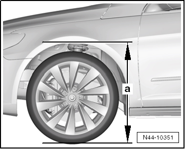
- Measure and record the ride height at all four wheels.
Note
- The Setting Device Basic Set -VAS6430/1- must not be moved on the calibration beam.
- The alignment stand must be in the lowest level position for the next step.
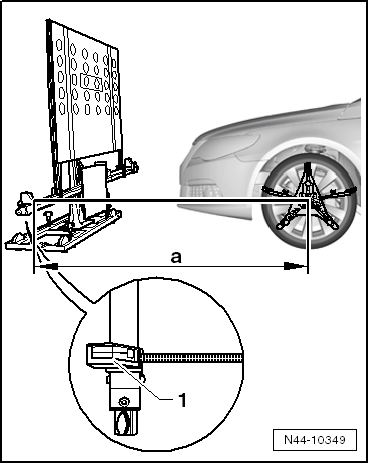
- Rotate the Setting Device Basic Set -VAS6430/1- upward just enough so that the calibration beam is parallel to the center of the measuring sensors on the front wheels, so that it is possible to correctly measure the distance measuring unit -1-.
- Distance measuring unit with spring tape measure and mounting pin
- Position the Setting Device Basic Set -VAS6430/1- at a distance -a- of 1500 mm +- 25 mm from the center of the wheel hub on the front wheels to the beam on the Setting Device Basic Set -VAS6430/1-.
Caution
- Distance -a- 1,500 mm +- 25 mm must be measured on both side of the vehicle and then the Setting Device Basic Set -VAS6430/1- must be aligned.
- Distance -a- must be the same on both sides of the vehicle.
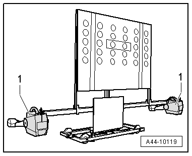
- Mount the front wheel measuring sensors -1- to the Setting Device Basic Set -VAS6430/1-.
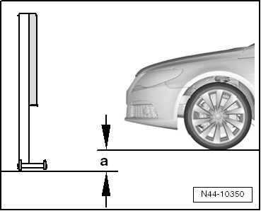
- Determine the height value -a- between the Setting Device Basic Set -VAS6430/1- contact patch and the wheel contact surface on the vehicle alignment platform and enter it in the alignment computer.

- Loosen the clamping bolt -arrow- and place the measuring bar -1- on the floor.
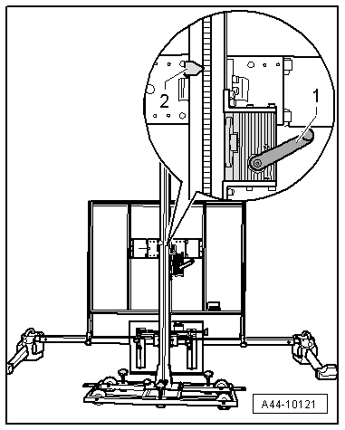
- Turn the crank -1- to adjust the Calibration Board For Lane Guard System -VAS6430/4- to the height specification -2- and then make a note of it.

If the specified height was reached, then the measuring bar -1- must be pushed slightly forward and secured with the locking bolt -arrow-.

- Level the bubble level -A- using the adjusting screw -1-.
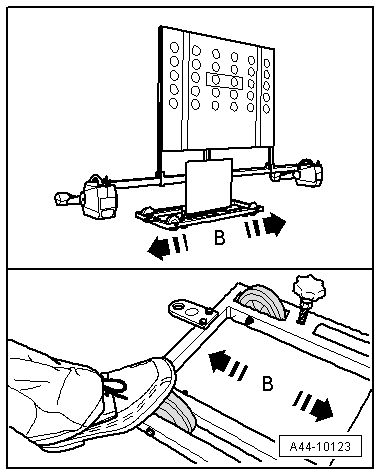
- Slide the Setting Device Basic Set -VAS6430/1- to the side -arrows B-, until the display in the wheel alignment computer is in the tolerance range.
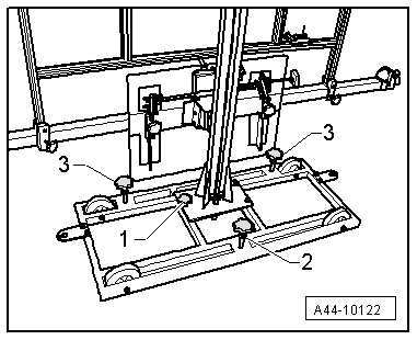
- By gently turning the adjustment screws -2 and 3- secure the Setting Device Basic Set -VAS6430/1- from rolling away.
- Turn the precision adjustment screw -1- until the display on the wheel alignment computer is located within the tolerance range.

- Level the bubble level -A- using the adjusting screw -1-.
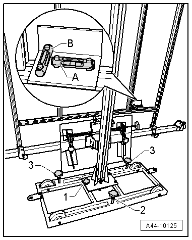
- Level the bubble level -B- using the adjusting screws -2 and 3-.
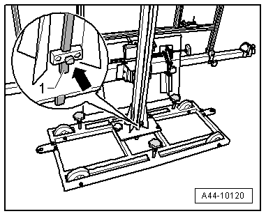
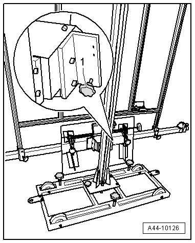
- Loosen the clamping bolt -arrow- and place the measuring bar -1- on the floor.

- Check specified height -2- one more time and adjust if necessary.
If the specified height was reached, then the measuring bar -1- must be pushed slightly forward and secured with the locking bolt -arrow-.
Perform any Subsequent Work using the Vehicle Diagnostic Tester.
- Switch the ignition on.
- Select "Guided Fault Finding" on the Vehicle Diagnostic Tester.

Body (Repair Group 01;27;50 through 97)
Electrical System (Repair Groups 01, 27 and 90 through 97)
01_OBD-capable systems
Driver Assistance Systems Front Camera -R242-
Driver assistance system camera, functions
A5 - Calibrate the control module (Repair Group 44)
Follow the instructions on the screen to perform the calibration.
Note
Next, in guided fault finding, determine the height of the body.

- Enter the recorded ride heights.
Special Tools
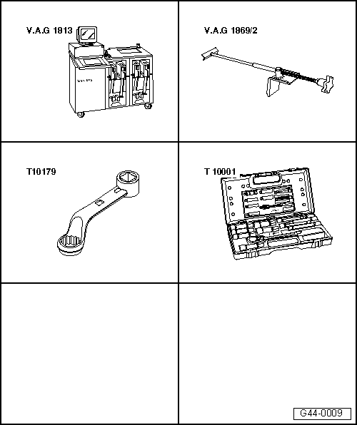
Special tools and workshop equipment required
- Wheel Alignment Computer -VAG1813- or VW/Audi approved wheel alignment devices
- Brake Pedal Actuator -VAG1869/2-.
- Insert Tool - 18mm -T10179-
- Shock Absorber Set -T10001-
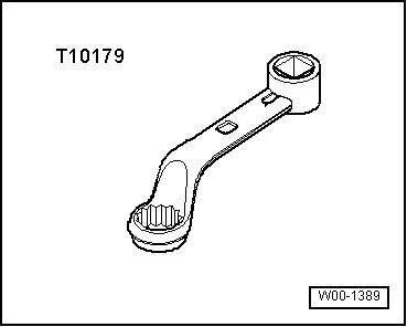
- Insert Tool - 18mm -T10179-
- Torque Wrench 1332 40-200Nm -VAG1332-
- Torque Wrench 1332 Insert - Open Ring Wrench - 24mm -VAG1332/11-
- Torque Wrench -VAG1410-
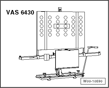
- Setting Device Basic Set -VAS6430/1-
- Wheel Alignment Computer
- Vehicle Diagnostic Tester
 Wheel/Tire Vibration, Causes and Solution
Vibration Causes
There are many causes for vibration. Vibration can also be caused by tire
wear, among other things. Tire wear caused by driving does not always develop
evenly over the entire tread. ...
 Steering
...
See More:
Volkswagen Tiguan Service and Repair Manual > Front Suspension: Front Suspension, Servicing
Overview - Front Axle
Chapter "Subframe, Stabilizer Bar and Control Arms".
Chapter "Wheel Bearing".
Chapter "Suspension Strut".
Chapter "Adaptive Chassis DCC Suspension Strut".
Wheel Bearing, Lifting to Curb Weight Position
Special tools and workshop equipment required
Engine and Gearbox ...
Volkswagen Tiguan Owners Manual
Volkswagen Tiguan Service and Repair Manual
- Body exterior
- Body Interior
- General Paint Information
- Paint
- Brake System
- Suspension, Wheels, Steering
- Wheel and Tire Guide
- Towing Guide
- Wheel and Tire Guide General Information
- Communication
- Electrical Equipment General Information
- Electrical Equipment from 06/2011
- Heating, Ventilation and Air Conditioning
- Refrigerant R134a Servicing
- 6-Speed Manual Transmission 02Q, OBB, and OFB
